 Hello, and welcome back to The 8-Bit Guy. So, in this episode, Im going to assemble
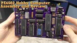
the PE6502 computer. This is a hobbyist computer thats meant
to be assembled at home, and this is actually a prototype. This computer is supposed to be Apple 1 compatible
so you should be able to run Apple 1 software on it and BASIC and stuff like that.
However, I spent a couple of hours talking
with Jason on the phone, hes the guy that designed this. And he said he likes to call it Apple 1.5
Compatible. Because its a bit more powerful than an
Apple 1 but now quite an Apple 2. But, whats really interesting is that what
hes actually working on now is making some changes that will allow this to run Commodore
BASIC.
And have the entire Commodore screen editor
and everything, which I think would be really cool. So, but Im going to go ahead and put this
one together and see what I can get running on it. Ill hook it up to my little handy TV here
and I dont know, lets assemble it and see if we can make it work!BThese zip-lock
bags should have all of the components to build this computer. Lets take them out and have a look at them.
Im not sure if there is any rhyme or reason
to the way these are packaged. Some things are grouped together in bags. It looks like all of the smaller components
are in this bag. Heres the actual board.
Its really nice and well made. Thats definitely a lot of parts to solder! Well, I guess I had better get out the soldering
station and all of my tools. But I also decided to print out the manual
as it was difficult to reference it quickly on my computer. Its quite a few pages, so I printed it
double sided to make it easier to manage.
All right, so Ive got my soldering iron,
Ive got the manual, and the board here. I also need a multi meter. One of the main reasons I need the multi meter
is for all of these resistors, because guess what? I cant read the codes on these resistors. Its great that he even included the color
charts for the resistors, but the problem is Im color blind and can rarely distinguish
brown from green or violet from blue.
I can see most of the other colors in the
spectrum, but its really hard for me to see brown and violet. So, I can use the meter to measure the resistors
so I make sure I use the right ones in the right places. Its also handy to have a picture here of
the final assembly because sometimes thats more helpful than a diagram. Im actually going to start with the resistors
because they are the most challenging for me due to my color blindness and Id just
like to get them over with.
And please dont send me a million emails
about those special sunglasses for colorblind people. Now, the good news is, a lot of these are
fairly obvious which value they are even without the multi meter because I can tell that, hey,
these 10 are obviously all of the same, and so I can look on the bill of materials and
see there are 10 identical resistors here, so I know which ones these are. And the same with these 7 here. So that just leaves these for me to measure.
So Ill start with these 10 here, and the
way Im going to do this is just to use the bill of materials. So lets look at all of these 1 kilo-ohm
resistors and Ill just start with this one which is R2. So Ill just look on the board and I can
clearly see R2 here. Pity theres no D2, right? Then wed have R2D2.
Ha Ha. Anyway, thats pretty much where all of
those 1K resistors go. So Ill put all of those in. Resistors are pretty easy to install.
Just bend the leads over like this. It doesnt really matter which direction
they go in, but it is nice to try to put all of them the same direction so it looks professional. Once in the hole, I usually bend the leads
out just a bit so it doesnt fall back through while Im soldering. Im still waiting on my soldering station
to warm up.
I forgot to turn it on earlier. Im using the default setting of 750 degrees. There we go, all ready! And, in case Ive never mentioned this,
soldering while trying to record it with a camera is actually really difficult because
youve got to get just the right angle to see the action, and make sure your hands and
other objects are out of the way. Im often contorting my body to accommodate
the tripod.
So, doing this without filming is much easier. So, when you see me shaking its not because
I am coming down with Parkinsons disease, its simply because Im probably in an
awkward position when Im trying to record it. OK, this is what good solder joints should
look like. Afterwords, you can use some cutters to remove
the excess leads.
So, now I just have a bunch more resistors
to do. Every time I put in a component, I mark it
off the list so I know its done. All right, so Ive managed to install all
of these resistors here and over here just by using reasoning without having to measure
anything or being able to read the codes. These are all thats left and Ill have
to measure them.
OK fast forward a bit, and Ive done all
of the resistors now. Notice I put them all in the same direction,
which makes it look nicer. For me, this was the most apprehensive part
of this project, so everything else should be a piece of cake! The next challenge is going to be all of these
tiny capacitors. Now the thing is, the text on these guys is
really small.
And my 42 year old eyes cannot read anything
this small anymore. So Ill be using this magnifying glass. This one is really handy because it has a
built in LED light. Anyway, as you can see, it will bring these
numbers into sharp focus, even for me! The good news is, these capacitors are apparently
all the same values.
The bad news is, they dont fit quite right
into the holes. The leads are too close together. So thats about as far down as it wants
to slide. This is not uncommon, actually.
The solution is to bend the leads a bit like
this. And so, yeah, it will go in a lot further
now. And so thats how it looks after being soldered
in place. Its not perfect, but it will work.
And so heres all of the little capacitors
now finished. Next up is this resistor pack. Basically it has 6 identical resistors inside
which share a common lead. And if you see that little dot on the left,
that represents pin 1.
And if you look on the board here, pin one
is also labeled so you know which direction to put this. So well just stick that in there, and solder
that from the other side. You sort of need 3 hands to install one of
these, but the way I usually do this is I. Hold the resistor pack from the other side
with one hand, then Ill bend my lead of solder out so it sort of holds itself near
the place I need to solder like this, and just bring the whole board to the solder.
All I need to do is get one pin soldered so
that it will hold it in place. Then the rest of the pins are easy to do. I should mention, by the way, that I tend
to like to install low-profile parts on a board first, before I install any taller parts. So thats just my preference, but it seems
to make it easier because the board will lay mostly flat and also because the smaller parts
wont get in the way of the big parts when it is time to insert them.
All right, so the next part Im going to
install is this 1 Mhz oscillator. This is what runs the clock on the 6502 processor. You may be wondering how to tell which direction
it goes. Well, if you look, theres this little circle
here, that represents pin 1.
And of course, pin 1 is clearly marked on
the board. So it just goes in nice and easy, like this. After soldering, these are a bit too long,
so Im going to cut them off. And next up is the 5 Mhz Crystal used for
the Parallax Propeller chip.
This has no specific orientation, you can
put it in either direction. And this fits in nice and flat. Theres exactly one diode in this project,
and here it is. Theres a stripe on the right side, which
indicates the polarity.
The good news is, this board is labelled really
well. Notice D1, thats where the diode goes and
theres a little stripe on the diagram. This will be pretty similar to the resistor
in that the leads get bent like so. And then right down it goes! Theres also exactly one transistor in this
build.
Now, the only thing you need to know in this
case, is that the transistor has a flat side. If you look at the board, it goes right there,
labelled Q1. And you can clearly see the flat side. The problem is the center lead will need to
be bent out some.
So I usually just bend the lead out like this. Then Ill use some needle nose pliers to
bent it back down like this. So now, it should fit in there better. Yeah, actually it fits great! So, Ill check that off the list.
Moving on, the next thing are these two momentary
switches, used for reset switches. One of them goes here, for resetting the propeller
chip, and the other goes over here for resetting the CPU. Now, these look kind of square like they might
go in more than one direction, but they are actually slightly rectangular and will only
fit one direction, so dont worry about that. Once it is lined up, it does take a bit of
force to pop it down.
The next thing Im going to solder in is
this pin header. Now, I will warn you that these are copper
all the way from one side to the other. So if you are holding this from one side while
you solder it from the other, it will conduct the heat really well and youre going to
burn your finger. So, this goes right here.
I suggest you be very aware which pins you
are touching when you go to solder this in! Of course, once you get the first pin soldered,
the rest of them are easy to do. Next up, Im going to start installing the
sockets, starting with these little ones. With any socket, be sure to double check this
little notch and make sure it lines up with a similar looking notch on the board. OK, so fast forwarding a bit, Ive got that
one installed, and that one installed, however, Ive got all of these sockets left to do.
These are going to be some of the most time
consuming parts to install. I tend to hold these with one hand, and I
do sort of like I did with the resistor pack, where I just put the solder right where I
need it to get that first pin done. Once thats done, I turn the board around
and solder the opposite pin on that socket. OK, so Ive got each corner soldered.
And these arent even very good solder joints. But thats okay because they will hold it
in place long enough for me to get some other pins soldered. At this point, I just want to double check
the board from all directions that the socket is in flat and that it is facing the right
direction. This would be a real pain to fix later.
Now I can solder the rest of the pins. Ill take this opportunity to mention that
I wouldnt really suggest a board like this for your very first soldering project. Id suggest something smaller and cheaper. But if youre a bit inexperienced, doing
a board like this is going to give you a lot of practice.
I would also like to mention I get a lot of
requests to make a tutorial on how to solder. But, honestly, there are several other youtube
channels that have that covered pretty well. I usually recommend a video by EEVBlog, which
I think covers about everything you need to know. I will also mention that Im using lead-based
solder, which in my opinion is easier to work with and does a better job.
However, I do have a fan going in the room
that helps to blow the fumes away from my face. I also always wash my hands when Im done
soldering to remove any residue from my hands. And some people might wonder why anyone would
want to assemble this stuff on their own. Well, to be honest, thats half of the fun
of a project like this.
Its sort of like a jig-saw puzzle for nerds. It will take you a few hours to assemble this
and then theres the anticipation of whether or not it will work when it is done! OK, so Ive got a problem. These are the only pieces I have left, and
I am missing a socket, which goes right here for the MAX232, which is the serial port controller. So, I guess what Im going to do is just
solder that chip in directly.
Which, is fine. I mean, you dont have to have a socket. The main benefit of a socket is to make it
easy to remove if you fry the chip or for whatever reason you might want to remove it. But we have sockets for all of the rest of
the chips, so I think well be fine.
OK, so now Im going to start installing
some of the taller objects, such as this header for the system bus. One problem you might notice is that he
he, gee its too big to fit. So no problem. Ill just use some cutters and cut it to
the right size.
And there we go, fits perfectly now! Next Ill do the PS/2 keyboard connector. PS/2 is kind of obsolete now, but at least
they were made in the millions so they should still be pretty easy to find. Anyway, so that goes on like so. And this is the next thing Im going to
put in.
This is the composite video connector. This is where the TV or monitor will connect. This thing has some pretty big pins on it,
thats to help with the stress of plugging and unplugging those cables. And the last of the connectors is the DC power
port, which is a fairly standard barrel connector.
I should mention this kit does not come with
a power supply. Anyway, so the connector goes here. Like so. And this thing also has some rather large
pins to help with the stress of connecting and disconnecting those cables.
I cant tell you how many laptops Ive
seen in my life that had broken power ports, usually because somebody tripped over the
wire. Moving along, this is the power LED. Now, youll notice that one leg here is
longer than the other. And that is the positive lead.
And when you look on the board, youll notice
a flat side, and that is for the negative. So the shorter leg will go in that side, like
so. Next up are two voltage regulators. One of these is for 5 volts for the 6502,
and then a 3.3 Volt version for the propeller chip.
Just line up the flat side with the big white
line there. Easy peasy. One of the last things left to do is install
these electrolytic capacitors. Im going to start with this big one here.
These do have a specific polarity so you need
to make sure you dont put them in backwards. Youll notice there is a stripe on this
one side here. And that needs to line up with the stripe
on the board. Now this board is different from any other
Ive seen when it comes to electrolytic caps.
So, this cap goes in C21, but it is drawn
as a square on the board. Im thinking maybe he originally planned
to use tantalum capacitors or something. Anyway, there is clearly a line showing where
the stripe goes so you can still line it up. But, it fits in there perfectly.
Ill bend the leads out to make it easier
to solder. And the soldering is almost done for this
job. Notice theres this spot to solder in a
switch, but no switch was actually included in the kit. This is if you wanted to add your own to whatever
case you might mount this in.
For me, Im just going to use some of these
left over pins and solder those in. Skipping ahead, those are in now, and Ill
just use this jumper here to act as a switch so that power is always on whenever the plug
is inserted. This would also make it really easy to connect
a power switch in the future. And heres all of the left over trash and
excess leads from assembly.
Now, the only thing that is left is to take
all of these chips and insert them into the sockets. So, lets get started! Im going to start with the 6502. Believe it or not, this is a brand new chip,
Western Digital still makes these, although I have no idea what uses them these days. But this is definitely the newest 6502 Ive
ever held in my hands.
Now Im going to put this in the socket. Ive actually bent the pins in just slightly
to help them line up. Its very important to make sure these pins
are lined up really well, otherwise when you go to push it down, one or more pins could
bend or break off. Same thing goes for these smaller chips, also
be sure to double check the direction and line up the notch! This is the firmware ROM chip.
Lets put this in! It takes a surprising amount of force to push
these things in. Next up is the propeller chip which will serve
as a video display since you can no longer buy the original Apple 1 video chips. And this is a static RAM chip, I believe 32K,
which is a lot more than the 4K of the original Apple 1. And THIS is a perfect example of pins not
cooperating when I tried to insert the chip.
Fortunately, I caught it before I pushed it
all the way down, so I can pull this out and bend them back. OK, so this thing is finally finished. All that is left to do is test it! Im going to need a power supply. I hope this is going to work.
It has the right connector and its actually
6.5 Volts, even though the instructions call for 9V, this should actually work because
its rated for anything between 6.5 And 9 volts. This actually comes from my speak and spell. Anyway, I think its going to work. And of course, well need a standard composite
video cable.
And Im going to use this old PS/2 keyboard. Its the perfect size for this project. So Ill plug in the keyboard, and then Ill
plug in the composite video cable. And now it is time for the smoke test.
If I did anything catastrophically wrong,
this is when Ill find out. Well, the good news is, nothing smoked or
popped. The bad news is, theres no video display. The power LED did come on, though.
OK, so I am not terribly surprised that it
didnt work. In fact, I would have been more surprised
if it had worked the first time. Theres always some little detail an an
assembly like this thats going to keep something from working, even the tiniest little
thing can keep it from booting. But, you know Im pretty sure I can get
this to work.
So, Im going to go ahead and start some
of my standard troubleshooting techniques. The first thing I wanted to do is check the
voltage at one of the chips to make sure were getting a steady 5V. And we are. So the power supply and regulator and all
of that is working fine.
The next thing I did was swap out this serial
eprom for the propeller chip. He sent me two of these for some reason, so
let me try the second one. And behold! It actually works. Well, sort of.
I entered into BASIC and just wanted to type
something, sure syntax error, thats expected. But then I discovered that any command I typed
gave me a syntax error. In fact, pretty much nothing worked right
on this board. It was very unstable! It would reboot constantly like every few
seconds, most commands I would type would either give strange results or just cause
the computer to reboot.
So, I knew something wasnt right. I knew there had to be some other problem
and I spent a lot of time troubleshooting the board, and I couldnt really find anything
wrong. Now, the manual had said in here to clean
all of the excess flux off the bottom of the board and that is something I had intended
to do. But, you know, I was kind of in a hurry so
I just thought, Ill skip that step for now and I didnt realize how important of
a step that is because flux apparently is conductive.
And, I guess that never really occurred to
me. But yeah, so I took some alcohol and a toothbrush
and I spent some time scrubbing the flux off of the board and then I actually rinsed it
in the sink and then it had to dry for a little while, actually had to let it dry for several
hours even after I used some compressed air to blow all of the water off. But after that, I turned it on, and it actually
works perfectly! Its perfectly stable now! So, lets take a tour and see what we can
do with this thing! So, it boots up into something called wozmon,
which stands for Wozniak Monitor. Its a really simple operating system.
Just for some examples of what you can do. If I type a memory address, like 2000, it
will simply reply and tell me what byte is stored at that address, in this case FC. Of course this is all in hexadecimal. If I wanted to see a large chunk of memory,
I can type the address, then a period, and then another address.
Then it will show me everything that is between
those addresses. There are two versions of BASIC stored in
ROM, so I can start one of those up by typing the starting address followed by an R. So,
now Im in integer BASIC. Of course, Im actually more comfortable
in Applesoft BASIC, so Ill use that one instead.
Of course, when demonstrating BASIC, everyone
has to write a small looping command to print something down the screen. So I wont disappoint. However, Ill write something maybe a little
bit more interesting. This is called a random maze.
We used to make these on the Commodore VIC-20
and 64. It doesnt look quite as good here because
the lines dont actually touch each other, but you can still see the maze if you concentrate. So you may be wondering what else you can
do with it, since there are no disk drives or SD card sockets or any way to copy over
any other programs. The original Apple 1 at least had a cassette
port interface.
This doesnt even have that. The only way to actually get new programs
onto this computer is to type them in with the keyboard either in BASIC or in machine
code. However, it does have a serial port, which
can make that a lot easier. So Ill just connect it up to one of my
old MS-DOS laptops.
I was going to use my favorite terminal program,
Telix, however, it doesnt seem to want to run on this laptop. So Ill just use Hyperterminal inside of
Windows 95 instead. According to the manual it needs to be set
to 115,200 bits per second. And its working, because that READY is
coming from the little computer.
OK, so what Im going to do now is click
transfer and send a text file over the serial port. Im going to pick microchess. As soon as I do this, youll see this machine
language code flying down the screen. As far as the computer is concerned, somebody
is typing this in on the keyboard.
It just so happens, the thing typing it is
another computer, so its really fast! Once its done, it automatically starts
the game, as thats the last command in the text file. Ive never played this before, so Im
not sure how it works. Ill pick zero, I guess. I have no idea what this means either.
And I cant figure out what Im doing
here either. I guess somehow Im supposed to indicate
which piece I want to move. Anyway, Ill have to read up on that later. Moving on, you can also send BASIC programs
much in the same way.
First, you just go into BASIC, in this case
Applesoft Basic, and Ill send over a text file for hangman. Again, its like Im typing in the hangman
game really fast. However, when it is done, it errors out. So Im thinking maybe it was designed for
integer BASIC instead, so Ill change over to that version and then try it again.
Skipping ahead a bit it works. Ill guess E, nope.. How about S, nope. U, maybe R, T, dang..
What is this? Well, after nearly trying the whole alphabet,
it turned out to be FLY. Lovely. Anyway, lets try another one. This is checkers.
Again, I cant quite figure out the commands
on this without reading the manual, so Ill do that later. All right, so I was not super impressed with
any of the games that are available for this little computer, so I thought Ill just
write my own. I was kind of thinking something along the
lines of Tetris. I figure I could probably write that in a
few hours if I didnt try to get too fancy.
The trouble is, I couldnt figure out how
to address the screen memory. And documentation for the Apple 1 is a bit
scarce and when you type that into google you always get results for the Apple I devices
like iPhones and iPads and stuff like that. Eventually, with enough asking around I finally
did find some documentation and one of the things I discovered about the Apple 1 design
which is really bizarre is that its impossible to actually address characters like anywhere
on the screen you want. So, the only thing that this computer can
do is it can send characters one at a time to a screen controller which will place the
characters at the bottom of the screen and then scroll everything else up.
But, its actually impossible to come back
up here and change some character thats already on the screen. The systems simply just not capable of
doing that. And, to illustrate why, I want to show you
this little diagram, king of showing a rough bus design of a traditional 8-bit computer
that would have been made during the 1980s. In a typical system of the 1980s, the CPU
would talk with a peripheral interface adapter, and thats usually what connects to things
like keyboards, joysticks, and disk drives.
And then theres the ROM and RAM on the
same bus with the CPU. And then the video chip usually shares some
of the RAM, and displays whatever it reads on an external monitor. The apple 1, however, has no joystick, no
disk drive, and to be honest, no video chip. At least not in the traditional sense.
What it does have is a rudimentary terminal
display like youd find in a dumb terminal of the 70s. And it is connected to the PIA chip, and the
CPU just sends characters over to be displayed. But the CPU has absolutely no control as to
where on the screen the character will end up. Thats all handled by those terminal chips.
Which means, coding a simple program like
Tetris is essentially impossible on the Apple 1. In fact, that explains a lot as to why those
programs like the chess would always redraw the entire board every time you make a move. So that really limits what you can do with
a computer like this. However, it does have the full system bus
available here on this pin header, so theres no reason you couldnt attach some other
kind of video chip, or even a little LCD screen like this.
In fact, I may mess with getting one of these
working for a future episode. But still, you know its a neat little computer,
and especially with the expansion socket that I mentioned, you could hack all kinds of things
on there. I mean heck, I bet you could get a SID chip
to work on there if you wanted to! But, Ill be much more impressed when somebody
creates something really similar to this that can run Commodore BASIC. You know, the actually screen editor, and
BASIC, and the Commodore kernel.
And it doesnt have to be compatible with
the Commodore 64 or VIC-20, as long as it can just run those things so that you can
get the environment and you know you could probably port over a lot of existing software,
so thats something that I would have a lot of fun playing with. But, I do think it definitely needs and SD-card
socket so that you can load and save programs to something at least a little bit more modern. Id probably try to design it myself, but
I simply dont have the time and its probably a little bit beyond my abilities. Still, if anybody else has a neat little home-brew
kit like this theyd like to send me, please, contact me and tell me about it and you know,
I may feature it here on the show in some future episode.
Otherwise, I guess that about wraps it up
for this one, so stick around and thanks for watching!.
No comments:
Post a Comment